Automatic UPS System Wiring Circuit Diagram (One Live Wire & Ordinary Wiring)
Automatic UPS / Inverter Connections
In case of an emergency breakdown when utility power is unavailable from the power house, we may use an automatic inverter / UPS wiring circuit with batteries to maintain uninterrupted power.
We will show two basic methods of wiring and connection of UPS / Inverter with batteries to the home distribution and main panel board.
- Auto UPS / Inverter with Two Wires
- Automatic USP / Inverter Wiring with One Live Wire
Note: To be on safe side, use 6 AWG (7/064″ or 16mm2) cable and wire size to connect the UPS to the main panel board.
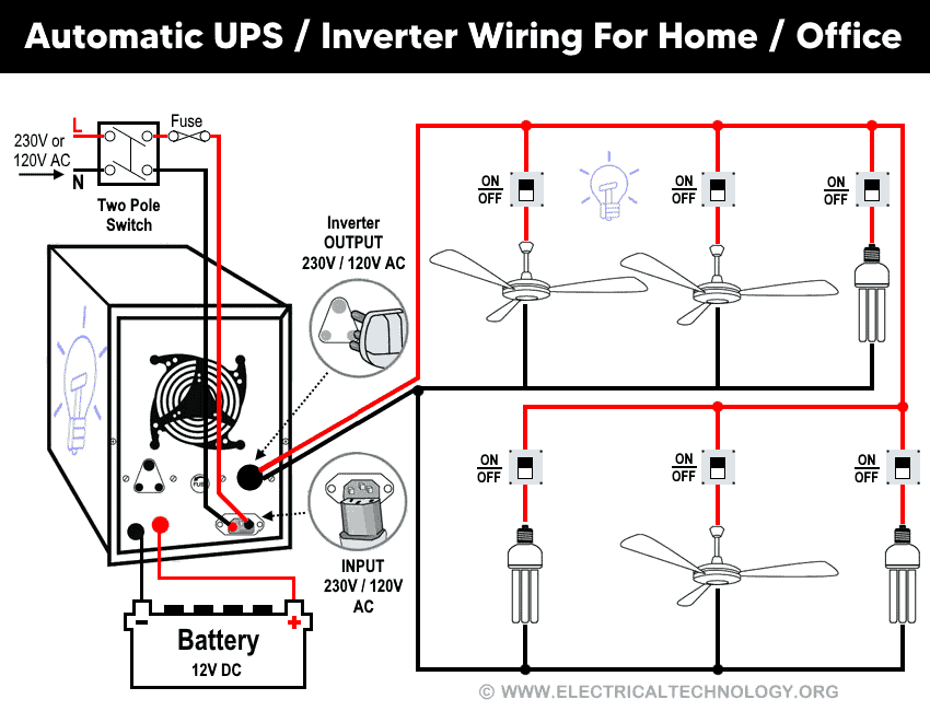
Automatic UPS / Inverter Wiring with two Wires.
No rocket science here. Just connect the outgoing Neutral and Live wires to the UPS. Now connect the two outgoing Neutral and Phase wires from UPS / Inverter (As output) to the appliances as shown in fig 1.
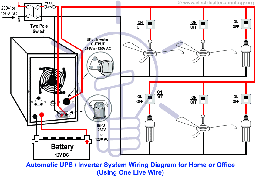
UPS / Inverter Wiring with Single Additional Live Wire
As a basic, we know that each load points should be connected through Live (Phase) and Neutral wire to operate normally. In case below, we have already connected the Phase & Neutral (from Power house to the utility pole & Distribution board then) to each electrical appliance i.e. Fans, Light points etc. That’s what we do in our distribution board for home wiring.
- Related Electrical Wiring Tutorial: UPS / Inverter Wiring Diagram With Auto & Manual Changeover Switch System.
Now, according to the UPS connection diagram below, connect an additional wire (Phase) to those appliances where we have already connected Phase and Neutral wires from the power house and distribution board (DB) (i.e., two wires as phase (Live), as shown in the figure below).
There is no need to connect an extra Neutral wire from the UPS since it is already installed and connected beforehand. In simple terms, you only need a live wire to connect to the appliances, as illustrated in Figure 2. Now, the question arises, “Why an extra Phase wire and not a Neutral?” Well, read the following explanation of the circuit’s working and operation to understand the idea.
You may also read:
- Single Phase Electrical Wiring Installation in Home – NEC & IEC
- Single Phase Electrical Wiring installation in a Multi-Story Building
Click image to enlarge
Working and Operation of UPS Connection
(1) When utility power is not available from power house
In this case, electric supply will continue through Phase wire (Output of UPS) which is connected to the batteries and UPS and then to electrical appliances (Note that Neutral is already connected). So the first one phase wire which has already connected before UPS installation (i.e. Live Wire from Main board to UPS) would be inactive because power supply is not available from power house. In this case, connected electrical appliances through the live wire from UPS / Inverter consume the stored electrical energy in the batteries without interruption.
Related Tutorials:
- Three Phase Electrical Wiring Installation in Home – NEC & IEC
- Three Phase Electrical Wiring Installation in a Multi-Story Building
(2) When power supply restores from power grid
Then power supply will continue through the Phase wire (Note that Neutral is already connected) which is connected to the UPS from main board (it will charge your battery as well) and then from UPS to connected electrical appliances. So the second one (phase or live wire) which is connected after UPS installation (i.e. One Live Wire from UPS) would be inactive because power supply is not available from UPS and batteries (Because it is Automatic UPS System).
Related Posts:
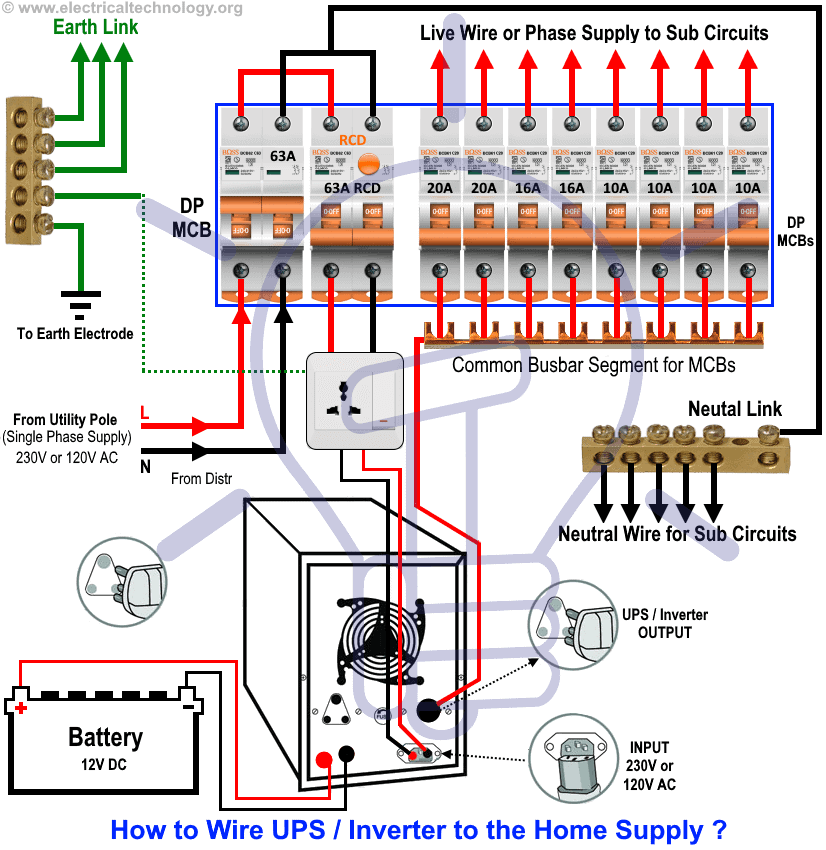
How to Connect a UPS / Inverter to the Switch Board?
The below fig 3 shows that how to connect a UPS / Inverter with batteries to the Main Distribution Unit for continues power supply in case of the utility power failure.
Additional wiring connection with connected load and appliances for two rooms in home. How to Connect Automatic UPS / Inverter to the Home Supply System?
Click image to enlarge
Wiring Color Code:
We have used Red for Live or Phase , Black for Neutral and Green for Earth Wire in single phase. You may use the specific area codes i.e. IEC – International Electrotechnical Commission (UK, EU etc) or NEC (National Electrical Code [US & Canada] where;
NEC:
Single Phase 120V AC:
Black = Phase or Line, White = Neutral and Green/Yellow = Earth Conductor
IEC:
Single Phase 230V AC:
Brown = Phase or Line, Blue = Neutral and Green = Earth Conductor.
General Precautions while playing with Electricity.
- Disconnect the power source before servicing, repairing or installing electrical equipments.
- Use the proper cable in size with this simple calculation method ( How to determine the suitable size of cable for Electrical Wiring Installation)
- Never try to work on electricity without proper guidance and care.
- Work with electricity only in presence of those persons who has good knowledge and practical work and experience who know how to deal with electricity.
- Read all the instructions, user manuals, cautions and follow them strictly.
- Doing your own electrical work is dangerous as well as illegal in some areas.Contact the licensed electrician or the power supply company before practicing any change in electrical wiring connection.
- The author will not be liable for any losses, injuries, or damages from the display or use of this information or if you try any circuit in wrong format. So please! Be careful because it’s all about electricity and electricity is too dangerous.
Related Posts:
Now If you still facing difficulties or don’t understand the wiring diagram, don’t hesitate to leave a comment or just check the other related step by step tutorials about UPS / Inverter Wiring Diagrams & Connections with description, and operation.
You may also read other Electrical Wiring Installation Tutorials.
- How to Wire Wire a Distribution Board [Single Phase]?
- How to Wire a Distribution Board with RCD – Single Phase ?
- Single Phase & Three Phase Wiring Diagrams (1-Phase & 3-Phase Wiring)
- Home Electrical Wiring Installation Diagrams & Tutorials
-
 What is Sag in Overhead Power Transmission Lines?
-
 Why is the Ground Wire Always Positioned Above the Overhead Power Lines?
-
 Betavolt Developed a Nuclear Battery Has a 50-Year Lifespan
-
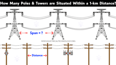 How Many Poles and Towers are Situated Within a 1-km Span?
-
 Why are Overhead Power Transmission Lines Not Insulated?
-
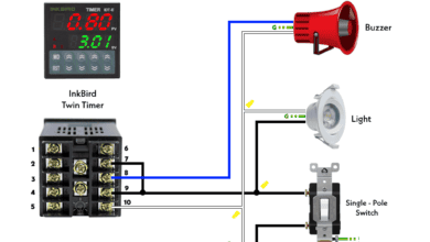 How to Wire Twin Timer for Repeated ON-Delay in Cycle Mode?