How to Determine the Suitable Size of Wire and Cable or Electrical Wiring Installation: Examples in Imperial and Metric Systems
The following step-by-step guide will show you how to find the right size of cable and wire, or any other conductor, for electrical wiring installations with solved examples in both British or English and SI Systems, i.e., Imperial and Metric Systems, respectively.
Keep in mind that selecting the proper wire size is crucial when sizing a wire for electrical installations. An inappropriate size of wire for larger loads with high current may lead to chaos, resulting in the failure of electrical equipment, hazardous fires, and serious injuries.
Factors Affecting the Wire Size
Current Carrying Capacity: The amount of current the wire needs to carry influences its size, ensuring it can handle the load without overheating.
Voltage Drop: For longer distances, consideration of voltage drop becomes crucial to maintain the efficiency and proper functioning of the electrical system.
Ambient Temperature: The environmental temperature affects the wire’s ability to dissipate heat, impacting its current-carrying capacity.
Insulation Type: Different insulating materials have varying thermal and electrical properties, influencing the overall performance and size requirements.
Installation Method: The manner in which the wire is installed, whether in conduit, cable trays, or exposed, can affect its ability to dissipate heat and, consequently, its size.
Conductor Material: Copper and aluminum have different conductivity and temperature characteristics, influencing their suitability for specific applications and, consequently, their sizing.
National Electrical Code (NEC) Guidelines: Adherence to electrical codes and standards is crucial, as they provide specifications and regulations for wire sizing to ensure safety and compliance.
Type of Load: The nature of the electrical load, whether resistive, inductive, or capacitive, can impact the wire size needed for optimal performance.
Cable Bundling: When multiple conductors are bundled together, there is a need to derate the ampacity of each conductor, affecting the overall wire size requirements.
Frequency of Operation: For applications involving alternating current (AC), the frequency of operation can influence the skin effect, affecting the effective resistance and thus impacting wire sizing.
Voltage Drop in a Cables
We know that all conductors, wires and cables (except superconductors) have some amount of resistance.
This resistance is directly proportional to the length and inversely proportional to the diameter of conductor i.e.
R ∝ l/a … [Laws of resistance R = ρ (L/a)]
Whenever current flows through a conductor, a voltage drop occurs. Generally, voltage drop may be neglected for short lengths of conductors. However, in the case of lower diameter and long-length conductors, we must take into account the considerable voltage drops for proper wiring installation and future load management.
According to the NEC – 316-10, add 20% of additional ampacity for every 100 feet of distance (for example between main panel and subpanel) to counter the voltage drop.
According tot the IEEE rule B-23, at any point between power supply terminal and installation, Voltage drop should not increase above 2.5% of the provided (supply) voltage.
Related Posts:
- How to Size a Load Center, Panelboards and Distribution Board?
- How to Determine the Right Size Capacity of a Subpanel?

Example:
If the supply voltage is 230V AC, then the value of allowable voltage drop should be;
- Allowable Voltage Drop = 230 x (2.5/100) = 5.75V
Similarly, if the supply voltage is 120V AC, the allowable voltage drop should be no more than 3V for separate branch circuit (120V x 2.5%) and 5% for feeder and branch circuits (120V x 5%). Refer to the NEC Code – 310-16 which stats 20% of additional ampacity for every 100 feet of distance should be added to counter the voltage drop in the circuit.
In electrical wiring circuits, voltage drops also occur from the distribution board to the different sub circuit and final sub circuits, but for sub circuits and final sub circuits, the value of voltage drop should be half of that allowable voltage drops (i.e. 2.75V of 5.5V as calculated above)
Normally, Voltage drop in tables is described in Ampere per meter (A/m) e.g. what would be the voltage drop in a one meter cable which caries one Ampere current?
There are two methods to define the voltage drop in a cable which we will discus below.
In SI (System international and metric system) voltage drop is described by ampere per meter (A/m).
In FPS (foot pound system) voltage drop is described in length based which is 100 feet.
- Update: Now you may also use the following electrical Calculators to find Voltage drop & the wire size in American wire gauge systems.
Related Posts:
- How to Find the Proper Size of Circuit Breaker? Breaker Calculator & Examples
- How to Determine the Number of Circuit Breakers in a Panel Board?
Tables & Charts for Proper Cable & Wire Sizes
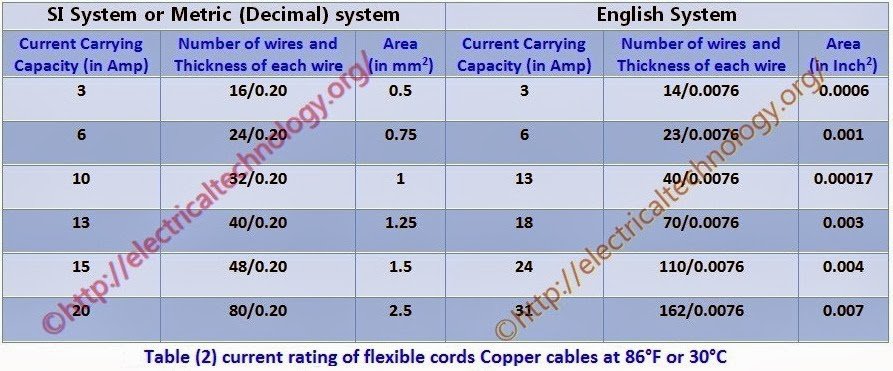
Below are the important tables which you should follow for determining the proper size of cable for Electrical Wiring Installation.
Click image to enlarge
Click image to enlarge
 Click image to enlarge
Click image to enlarge
 Click image to enlarge
How to Find the Voltage Drop in a Cable?
To find voltage drop in a cable, follow the simple steps given below.
- First of all, find the maximum allowable voltage drop.
- Now, find the load current.
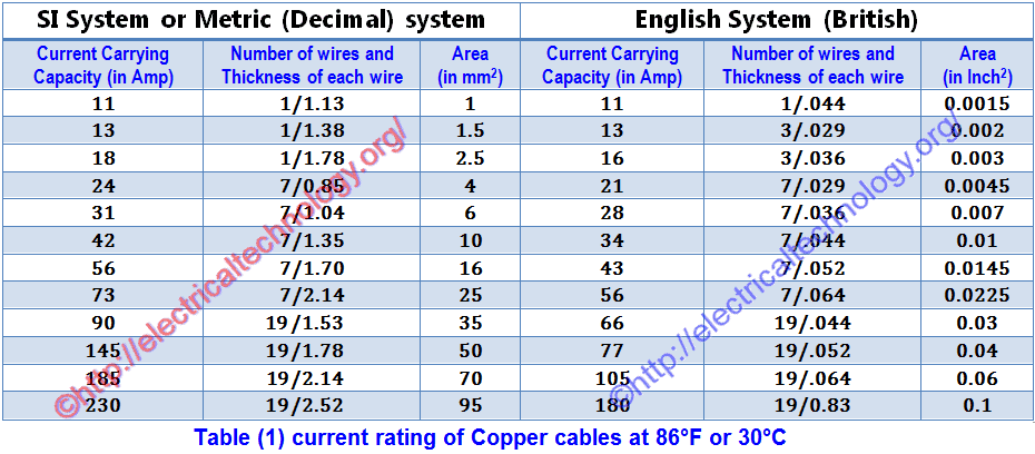
- Now, according to the load current, select a proper cable (which current rating should be nearest to the calculated load current) from table 1.
- From Table 1, find the voltage drop in meter or 100 feet (what system you prefer) according its rated current.
(Stay cool :) We will follow both methods and systems for finding voltage drops (in meters and 100 feet) in our solved example for whole electrical installation wiring).
- Now, calculate the voltage drop for the actual length of the wiring circuit according to its rated current with the help of following formulas.
(Actual length of circuit x volt drop for 1m) /100 ===> to find Volt drop in per meter.
(Actual length of circuit x volt drop for 100ft) /100 ===> to find volt drop in 100 feet.
- Now multiply this calculated value of volt drop by load factor where;
Load factor = Load Current to be taken by Cable/ Rated Current of Cable given in the table.
- This is the value of Volt drop in the cables when load current flows through it.
- If the calculated value of voltage drop is less than the value calculated in step (1) (Maximum allowable voltage drop), than the size of selected cable is proper
- If the calculated value of voltage drop is greater than the value calculated in step (1) (Maximum allowable voltage drop), than calculate voltage drop for the next (greater in size) cable and so on until the calculated value of voltage drop became less than the maximum allowable voltage drop calculated in step (1).
Related Posts:
- How to Size a Generator? Portable, Backup & Standby for Home & Commercial Applications
- How to Determine the Suitable Size of Inverter for Home Appliances?
How to Determine the Proper Cable & Wire Size for a Given Load?
Below are solved examples demonstrating how to find the proper cable size for a given load.
For a given load, cable size may be determined using various IEC and NEC tables (such Article 310 – Table – 310.15 (B) 16. However, it is crucial to keep in mind the role of ambient temperature and voltage drop for distance between main panel and subpanel.
When determining the size of cable for a given load, take into account the following general rules of thumbs.
- For a given load, apart from the known current value, there should be a 20% additional margin as safety factor and for future or emergency needs (required by both NEC (220-2) and IEC/IEEE).
- In the NEC – 316-10, add an additional 20% ampacity to the wire size if the length of the wire exceeds 100 ft (between the main panel and the subpanel).
- In IEC, the voltage drop should be limited to 1.25%, and for the final sub-circuit, the voltage drop should not exceed 2.5% of the supply voltage from the energy meter to the distribution board.
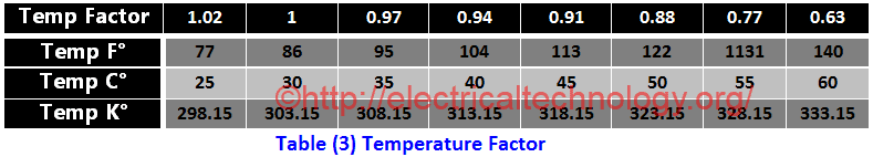
- Consider the change in temperature, which affects the ampacity (current carrying capacity) of the wire. When needed, use the temperature factor (Table 3 and related NEC table given at the end of this article).
- Additionally, take the load factor (diversity factor or demand factor (NEC – 220.42 and (220.45)) into consideration when determining the size of the cable.
- When calculating the cable size, consider the type of wiring system; for example, in an open wiring system, temperature would be low, but in conduit wiring, temperature increases due to the absence of air.
Related Posts:
- Electrical Cable & Wire Size Calculator for Copper & Aluminum
- Wire & Cable Size in AWG Calculator for 1 and 3-Phase Load
- Voltage Drop in Wire & Cable Calculator
Solved Examples of Proper Cable & Wire Size
The following examples illustrate how to determine the proper size of cables for electrical wiring installations. These examples will make it easy to understand the method of determining the proper cable size for a given load in both single phase ad three phase wiring installations.
Example 1 – (Imperial Followed by NEC)
What is the right size of wire for a 1,920 W load circuit supplied by 120V AC at 60°C (140°F)?
Solution:
First of all, let’s determine the current in amperes using basic Ohm’s Law that will flow from the 120V breaker to the 1.92kW load.
I (in Amps) = P (in Watts) ÷ V (in Volts)
I = 1,920 W ÷ 120 V
I = 16 Amp
Now, add a safety factor of 1.25, as per NEC Code 220-2 for branch circuits, feeders, and service loads. This code specifies that only 80% of the branch circuit load should be connected to the circuit for the ampacity of the wire for any load. For instance, a 10-ampere breaker should be used for an 8-ampere load point. This way:
I = 16 amp x 1.25
I = 20 Amp.
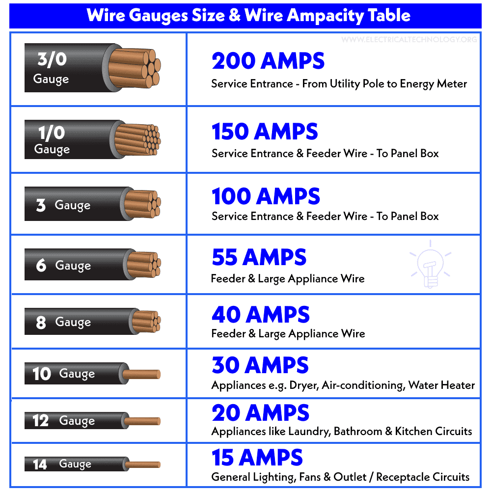
Now, If you see in the AWG wire size chart and NEC Table 310-15B (16) Article 310.60 (given below), the right size for 20 amp circuit is #12 AWG.
Example 2 – (240V and Distance Involved)
Find the Proper wire size for 2,400 W load circuit supplied by 240V at a distance of 100 feet?
Solution:
Find the current using the following formula (same as mentioned above)
Current = Power ÷ Voltage
I = 2,400 W ÷ 240 V
I = 10 Amperes
Now, multiply the safety factor of 1.25 (80% of load should be connected of the rated ampacity) to the calculated amperage.
As the circuit is 100ft away, add additional 20% ampacity to the calculated value (according to the NEC Code – 310-16) to counter the voltage drop in the circuit.
Total Amps = 12.5A + 2.5A = 15 Amperes.
According to NEC table 310-15B and AWG wire size chart, the suitable wire size for 15 amp circuit is #14 AWG for copper at 60°C (140°F).
Warning: It is always advisable to use copper wire instead of aluminum for better conductivity and reduced power consumption. If it is necessary to use aluminum, the wire size in AWG may differ compared to a copper conductor. Refer to the tables given below to select the wire size accordingly in the case of using aluminum.
In addition, it is recommended to use solid wire instead of stranded wire for a better grip, reduced sparks, and a protected environment from shock and fire.
Example 3 – (Imperial, British or English System)
For an electrical wiring installation in a building, where the total load is 4.5kW and the total length of cable from the energy meter to the sub-circuit distribution board is 35 feet, with a supply voltage of 220V and a temperature of 40°C (104°F), find the most suitable size of cable if wiring is installed in conduits.
Solution:
- Total Load = 4.5kW = 4.5 x 1000W = 4500W
- 20% additional load = 4500 x (20/100) = 900W
- Total Load = 4500W + 900W = 5400W
- Total Current = I = P ÷ V = 5400W /220V = 24.5A
Now select the size of cable for load current of 24.5A (from Table 1) which is 7/0.036 (28 Amperes). It means we can use 7/0.036 cable according to table 1.
Now, check the selected (7/0.036) cable with the temperature factor in Table 3. The temperature factor is 0.94 (from Table 3) at 40°C (104°F), and the current carrying capacity of (7/0.036) is 28A. Therefore, the current carrying capacity of this cable at 40°C (104°F) would be:
Current rating for 40°C (104°F) = 28 x 0.94 = 26.32 Amp.
Since the calculated value (26.32 Amp) at 40°C (104°F) is less than the current carrying capacity of the (7/0.036) cable, which is 28A, this size of cable (7/0.036) is also suitable with respect to temperature.
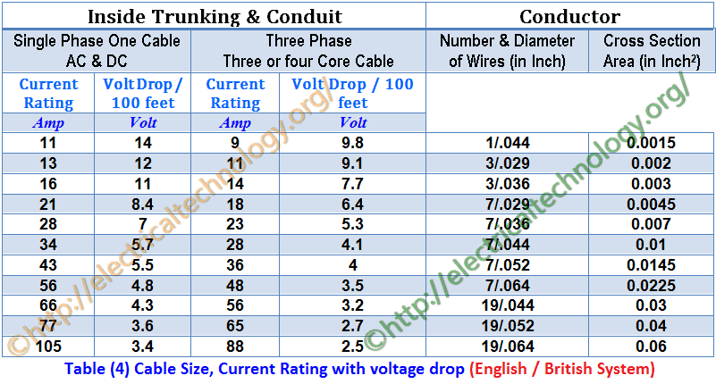
Now find the voltage drop for 100 feet for this (7/0.036) cable from Table 4 which is 7V, But in our case, the length of cable is 35 feet. Therefore, the voltage drop for 35 feet cable would be;
Actual Voltage drop for 35 feet = (7 x 35/100) x (24.5/28) = 2.1V
And Allowable voltage drop = (2.5 x 220)/100 = 5.5V
Here, the actual voltage drop (2.1V) is less than the maximum allowable voltage drop of 5.5V. Therefore, the most appropriate and suitable cable size for that given load in the electrical wiring installation is (7/0.036).
Related Posts:
- How to Find the Voltage & Ampere Rating of Switch, Plug, Outlet & Receptacle
- How to calculate the Cable size for LT & HT Motors?
- How to Find the Size of Earth Conductor, Earthing Lead & Earth Electrodes?
Example 4 – (SI / Metric / Decimal System)
What type and size of cable suits for given situation
- Load = 5.8kW
- Volts = 230V AV
- Length of Circuit = 35 meter
- Temperature = 35°C (95°F)
Solution:
Load = 5.8kW = 5800W
Voltage = 230V
Current = I = P/V = 5800 / 230 = 25.2A
20% additional load current = (20/100) x 5.2A = 5A
Total Load Current = 25.2A + 5A = 30.2A
Now select the size of cable for load current of 30.2A (from Table 1) which is 7/1.04 (31 Amperes). It means we can use 7/0.036 cable according to the table 1.
Now check the selected (7/1.04) cable with temperature factor in Table 3, so the temperature factor is 0.97 (in table 3) at 35°C (95°F) and current carrying capacity of (7/1.04) is 31A, therefore, current carrying capacity of this cable at 40°C (104°F) would be;
Current rating for 35°C (95°F) = 31 x 0.97 = 30 Amp.
Since the calculated value (30 Amp) at 35°C (95°F) is less than that of current carrying capacity of (7/1.04) cable which is 31A, therefore this size of cable (7/1.04) is also suitable with respect to temperature.
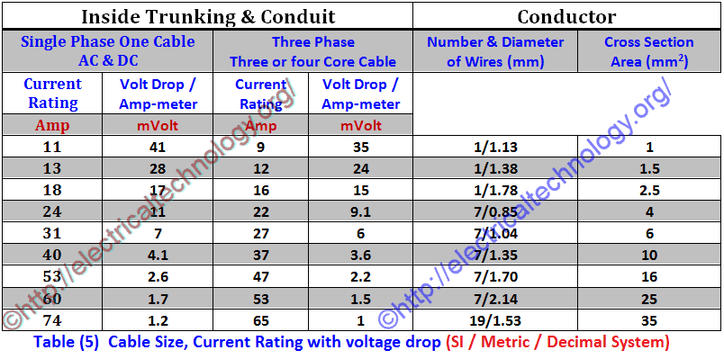
Now find the voltage drop for per ampere meter for this (7/1.04) cable from (Table 5) which is 7mV, But in our case, the length of cable is 35 meter. Therefore, the voltage drop for 35 meter cable would be:
Actual Voltage drop for 35meter =
= mV x I x L
= (7/1000) x 30×35 = 7.6V
And Allowable voltage drop = (2.5 x 230)/100 = 5.75V
Here the actual Voltage drop (7.35V) is greater than that of maximum allowable voltage drop of 5.75V. Therefore, this is not a suitable size of cable for that given load. So we will select the next size of selected cable (7/1.04) which is 7/1.35 and find the voltage drop again.
According to Table (5) the current rating of 7/1.35 is 40 Amperes and the voltage drop in per ampere meter is 4.1 mV (See table (5)). Therefore, the actual voltage drop for 35 meter cable would be;
Actual Voltage drop for 35 meter =
= mV x I x L
(4.1/1000) x 40×35 = 7.35V = 5.74V
This drop is less than that of maximum allowable voltage drop. So this is the most appropriate and suitable cable or wire size.
Related Posts:
- How To Locate Faults In Cables? Cable Faults, Types & Causes
- How to calculate the value of resistor for LEDs (with different types of LED’s circuits)
Example 5
Following Loads are connected in a building:-
Sub-Circuit 1
- 2 lamps each o 1000W and
- 4 fans each of 80W
- 2 TV each of 120W
Sub-Circuit 2
- 6 Lamps each of 80W and
- 5 sockets each of 100W
- 4 lamps each of 800W
If supply voltages are 230 V AC, then calculate circuit current and Cable size for each Sub-Circuit?
Solution:
Total load of Sub-Circuit 1
= (2 x 1000) + (4 x 80) + (2×120)
= 2000W + 320W + 240W = 2560W
Current for Sub-Circuit 1 = I = P/V = 2560/230 = 11.1A
Total load of Sub-Circuit 2
= (6 x 80) + (5 x 100) + (4 x 800)
= 480W + 500W + 3200W= 4180W
Current for Sub-Circuit 2 = I = P/V = 4180/230 = 18.1A
Therefore, Cable suggested for sub circuit 1 = 3/.029” (13 Amp) or 1/1.38 mm (13 Amp)
Cable suggested for Sub-Circuit 2 = 7/.029” (21 Amp) or 7/0.85 mm (24 Amp)
Total Current drawn by both Sub-Circuits = 11.1A + 18.1A = 29.27 A
So cable suggested for Main-Circuit = 7/.044″ (34 Amp) or 7/1.04 mm (31 Amp)
Related Posts:
- American Wire Gauge “AWG” Chart – Wire Size & Ampacity Table
- American Wire Gauge (AWG) Calculator – AWG Size Chart & Table
- Standard Wire Gauge “SWG” Calculator – SWG Size Chart & Table
Example 6
A 10H.P (7.46kW) three phase squirrel cage induction motor of continuous rating using Star-Delta starting is connected through 400V supply by three single core PVC cables run in conduit from 250feet (76.2m) away from multi-way distribution fuse board. Its full load current is 19A. Average summer temperature in Electrical installation wiring is 35°C (95°F). Calculate the size of the cable for the motor?
Solution:
- Motor load = 10H.P = 10 x 746 = 7460W *(1H.P = 746W)
- Supply Voltage = 400V (3-Phase)
- Length of cable = 250feet (76.2m)
- Motor full load Current = 19A
- Temperature factor for 35°C (95°F) = 0.97 (From Table 3)
Now select the size of cable for full load motor current of 19A (from Table 4) which is 7/0.36” (23 Amperes) *(Remember that this is a 3-phase system i.e. 3-core cable) and the voltage drop is 5.3V for 100 Feet. It means we can use 7/0.036 cable according Table (4).
Now check the selected (7/0.036) cable with temperature factor in table (3), so the temperature factor is 0.97 (in table 3) at 35°C (95°F) and current carrying capacity of (7/0.036”) is 23 Amperes, therefore, current carrying capacity of this cable at 40°C (104°F) would be:
Current rating for 40°C (104°F) = 23 x 0.97 = 22.31 Amp.
Since the calculated value (22.31 Amp) at 35°C (95°F) is less than that of current carrying capacity of (7/0.036) cable which is 23A, therefore this size of cable (7/0.036) is also suitable with respect to temperature.
Load factor = 19/23 = 0.826
Now find the voltage drop for 100feet for this (7/0.036) cable from table (4) which is 5.3V, But in our case, the length of cable is 250 feet. Therefore, the voltage drop for 250 feet cable would be;
Actual Voltage drop for 250feet = (5.3 x 250/100) x 0.826 = 10.94V
And maximum Allowable voltage drop = (2.5/100) x 400V= 10V
Here the actual Voltage drop (10.94V) is greater than that of maximum allowable voltage drop of 10V. Therefore, this is a not a suitable size of cable for the given load. So we will select the next size of selected cable (7/0.036) which is 7/0.044 and find the voltage drop again. According to Table (4) the current rating of 7/0.044 is 28 Amperes and the volt drop in per 100 feet is 4.1V (see Table 4). Therefore, the actual voltage drop for 250 feet cable would be;
Actual Voltage drop for 250 feet =
= Volt drop per 100 feet x length of cable x load factor
= (4.1/100) x 250 x 0.826 = 8.46V
And Maximum Allowable voltage drop = (2.5/100) x 400V= 10V
The actual voltage drop is less than that of maximum allowable voltage drop. So this is the most appropriate and suitable cable size for electrical wiring installation in a given situation.
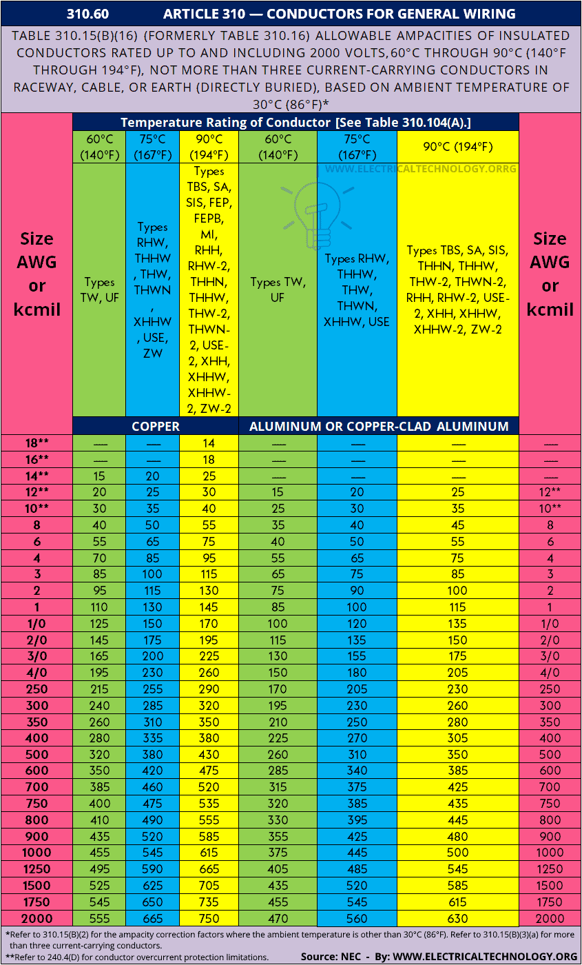
NEC Wire Size Table 310.15(B)(16) (formerly Table 310.16) & Chart
NEC (National Electrical Code) Table 310.15(B)(16) (formerly Table 310.16) – 310.60 – ARTICLE 310 – Conductors for General Wiring & Allowable Ampacities of Conductors & Wire Sizes based on AWG (American Wire Gauge).
| 310.60 ARTICLE 310 — CONDUCTORS FOR GENERAL WIRING | |||||||
| Table 310.15(B)(16) (formerly Table 310.16) Allowable Ampacities of Insulated Conductors Rated Up to and Including 2000 Volts, 60°C Through 90°C (140°F Through 194°F), Not More Than Three Current-Carrying Conductors in Raceway, Cable, or Earth (Directly Buried), Based on Ambient Temperature of 30°C (86°F)* | |||||||
| Size AWG or kcmil | Temperature Rating of Conductor [See Table 310.104(A).] | Size AWG or kcmil | |||||
| 60°C (140°F) | 75°C (167°F) | 90°C (194°F) | 60°C (140°F) | 75°C (167°F) | 90°C (194°F) | ||
| Types TW, UF | Types RHW, THHW, THW, THWN, XHHW, USE, ZW | Types TBS, SA, SIS, FEP, FEPB, MI, RHH, RHW-2, THHN, THHW,
THW-2, THWN-2, USE-2, XHH, XHHW, XHHW-2, ZW-2 |
Types TW, UF | Types RHW, THHW, THW, THWN, XHHW, USE | Types TBS, SA, SIS, THHN, THHW,
THW-2, THWN-2, RHH, RHW-2, USE-2, XHH, XHHW, XHHW-2, ZW-2 |
||
| COPPER | ALUMINUM OR COPPER-CLAD ALUMINUM | ||||||
| 18** | — | — | 14 | — | — | — | — |
| 16** | — | — | 18 | — | — | — | — |
| 14** | 15 | 20 | 25 | — | — | — | — |
| 12** | 20 | 25 | 30 | 15 | 20 | 25 | 12** |
| 10** | 30 | 35 | 40 | 25 | 30 | 35 | 10** |
| 8 | 40 | 50 | 55 | 35 | 40 | 45 | 8 |
| 6 | 55 | 65 | 75 | 40 | 50 | 55 | 6 |
| 4 | 70 | 85 | 95 | 55 | 65 | 75 | 4 |
| 3 | 85 | 100 | 115 | 65 | 75 | 85 | 3 |
| 2 | 95 | 115 | 130 | 75 | 90 | 100 | 2 |
| 1 | 110 | 130 | 145 | 85 | 100 | 115 | 1 |
| 1/0 | 125 | 150 | 170 | 100 | 120 | 135 | 1/0 |
| 2/0 | 145 | 175 | 195 | 115 | 135 | 150 | 2/0 |
| 3/0 | 165 | 200 | 225 | 130 | 155 | 175 | 3/0 |
| 4/0 | 195 | 230 | 260 | 150 | 180 | 205 | 4/0 |
| 250 | 215 | 255 | 290 | 170 | 205 | 230 | 250 |
| 300 | 240 | 285 | 320 | 195 | 230 | 260 | 300 |
| 350 | 260 | 310 | 350 | 210 | 250 | 280 | 350 |
| 400 | 280 | 335 | 380 | 225 | 270 | 305 | 400 |
| 500 | 320 | 380 | 430 | 260 | 310 | 350 | 500 |
| 600 | 350 | 420 | 475 | 285 | 340 | 385 | 600 |
| 700 | 385 | 460 | 520 | 315 | 375 | 425 | 700 |
| 750 | 400 | 475 | 535 | 320 | 385 | 435 | 750 |
| 800 | 410 | 490 | 555 | 330 | 395 | 445 | 800 |
| 900 | 435 | 520 | 585 | 355 | 425 | 480 | 900 |
| 1000 | 455 | 545 | 615 | 375 | 445 | 500 | 1000 |
| 1250 | 495 | 590 | 665 | 405 | 485 | 545 | 1250 |
| 1500 | 525 | 625 | 705 | 435 | 520 | 585 | 1500 |
| 1750 | 545 | 650 | 735 | 455 | 545 | 615 | 1750 |
| 2000 | 555 | 665 | 750 | 470 | 560 | 630 | 2000 |
|
|||||||
Here is the NEC table as a chart (image format to downloads as a reference)
Click image or open in a new tab to enlarge
Related Posts:
- How to Find the Right Wire Size for 100 Amp in AWG?
- How to Wire 120V & 240V Main Panel? Breaker Box Installation
- How to Wire a Subpanel? Main Lug Installation for 120V/240V
- How to Wire Single-Phase, 230V Consumer Unit with RCD?
- How to Wire a Garage Consumer Unit?
- How to Connect a Portable Generator to the Home Supply – 4 Methods
- How to Connect Automatic UPS / Inverter to the Home Supply System?
- How to Calculate the Suitable Capacitor Size in Farads & kVAR for Power factor Improvement
- How to Convert Capacitor Farads into kVAR & Vice Versa (For Power factor improvement)
- How to Test a Capacitor using Digital & Analog Multimeter. 8 Methods
- How to Check the Value of Burnt Resistor. 3 Handy methods
- How To: Electrical & Electronics Tutorials
- Basic Electrical Wiring Installation Tutorials
-
 What is the Power Angle in a Power Transmission Line?
-
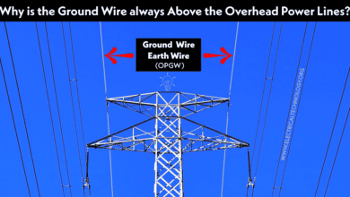 Why is the Ground Wire Always Positioned Above the Overhead Power Lines?
-
 What is the Minimum Ground Clearance for Overhead Power Line?
-
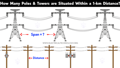 How Many Poles and Towers are Situated Within a 1-km Span?
-
 Why are Overhead Power Transmission Lines Not Insulated?
-
 Why are “High Voltage” Signs used when Only Current Kills?