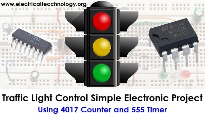
Traffic Light Control Circuit – Simple Electronic Project
Introduction
Traffic Lights are used to control vehicular traffic on the road and publics streets. In the modern era, where everyone owns different types of vehicles resulting in a rise in the numbers of vehicles which leads to traffic jams and rush on the busy routes. That’s why traffic lights are mandatory for smooth traffic to avoid the traffic jams and accidents.
Basically, there are three lights in the traffic signal, each having a different message for the drivers. Red light (upper one) asks the driver to yield at the intersection, green light (last one) gives the driver free license to drive through the intersection whereas the yellow light (middle one) alerts the driver to wait if the next light is red one or get ready to go / turn the engine ON if the green light is next.
Traffic lights have proved to be an amazing way to stop vehicular collisions and control the traffic jams and divert the traffic in smooth lanes. Let’s see how to make a simple traffic light contol system using basic electonic components as follows.
Project Proposal:
As the name of the project “Traffic Light Control Circuit” suggests, the fundamental idea of this simple electronic project is to control the traffic via lighting signals. It can be used to avoid vehicular collisions and traffic jams as the system ensures the smooth flow of traffic even on the busy routes. This project is just a one-way traffic controller, although it can be further modified as well. In short, the circuit can be used to provides the instructions to the driver via lighting symbols whether to drive through, stop or yield at the intersection.
Control Lights indication:
There are three control lights or signals, which will provide the instruction to the driver.
- RED light – instructs the driver to STOP at the intersection.
- YELLOW light– instructs the driver to WAIT (If red light is next) or GET READY (if green light is next)
- GREEN light – instructs the driver to GO through the intersection.
Components Requirements:
Following is the list of the basic components, which we will be using to make our traffic light Control System.
- 9V Battery (Input battery)
- 100K, 22K and 330 ohm resistors
- 1µF, 10µF and 2.2mF capacitors
- Six 1N4148 diodes
- 555 timer IC (As a pulse generator)
- 4017 IC counter (Main IC of the circuit)
- 1M Potentiometer (Controls the timing of pulse generated by 555 timer)
- Red, Yellow and Green LEDs. (Output lighting signals)
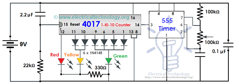
Circuit Diagram of Traffic Light Control mini Project
Click image to enlarge
Working Principle:
This traffic light circuit is designed based on a counter IC, which is mainly used in sequential circuits where a sequential circuit is used to count the numbers in the series. This way, we may call it a sequential traffic light system.
The working and operation of traffic lights control circuit, the main IC is 4017 counter IC which is used to glow the Red, Yellow and Green LED respectively. The 555 timer acts as a pulse generator providing an input to the 4017 counter IC.
The glowing time of certain LED lights totally depends upon the 555 timer’s pulse, which we can control via the potentiometer, so if you want to change the time of glow for a specific LED, you can do so by varying the potentiometer which is used to handle the setting of timing durations.
As the LEDs are not connected directly with the 4017 counter, hence the lights won’t be stable all the time. For this reason, we have used the combination of 1N4148 diodes and the LEDs in order to get the appropriate output lighting signals. The Main drawback of this circuit is that you are unable to set an exact timing using this configuration, however you will have the accurate estimated time period during the circuit operation.
Related Basic Projects with Circuit Diagrams:
- Automatic Street Light Control System using LDR & Transistor BC 547
- Automatic Bathroom Light Switch Circuit Diagram and Operation
- Automatic Doorbell with Object Detection By Arduino
- Automatic LED Emergency Light Circuit
- Automatic Night Lamp Using Arduino
- Automatic Plant Watering & Irrigation System – Circuit, Code & Project Report
- Fully Automatic Water Level Controller using SRF04
- Automatic Railway Gate Control System – Circuit & Source Code
-
 How to Wire Twin Timer for Repeated ON-Delay in Cycle Mode?
-
 Wire Twin Timer in Repeat Cycle & One-Shot Mode for 120V/240V Motors?
-
 How to Wire Twin Timer for 120V/240V Circuits – ON/OFF Delay
-
 How to Wire Multifunction ON/OFF Delay Timer for 120V/240V Motors?
-
 How to Wire One-Shot Timer using Twin Timer For Delay?
-
 How to Control 120V & 240V Water Heater using ST01 Timer and Contactors?