Troubleshooting
-

Circuit Diagram of Digital Voltmeter Using Using ICL7107
Schematic Diagram of Digital Voltmeter With LCD Display Using ICL7107 – DIY Project Kit The ICL7107 is a high-precision analog-to-digital converter (ADC) that can be used to build a digital…
Read More » -
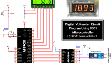
Circuit Diagram of Digital Voltmeter Using 8051 Microcontroller
Schematic Diagram of Digital Voltmeter With LCD Display Using AT89C51 Microcontroller With Source Code A digital voltmeter is an electronic instrument that measures the voltage of an electrical signal. It…
Read More » -
Types of Faults in Electrical Power System
Different Types of Faults in Power Systems. Causes & Effects, Severity & Occurrence and Fault Protection Devices In modern days, we cannot imagine our daily life without electricity. Our homes, offices…
Read More » -
American Wire Gauge “AWG” Chart – Wire Size & Ampacity Table
AWG – American Wire Gauge Chart – Wire Size & Amps Rating Table American Wire Gauge “AWG” is one of the important and standard tools in the US NEC (National…
Read More » -
Top & Best Books & Guides for Electricians and Apprentices
Best Books for Electricians and Apprentices in 2022 The following list provides a series of authentic books and guides which will properly help you to become an ultra pro max…
Read More » -
What happens if You Connect a 3-Φ Induction Motor to 1-Phase Supply?
What will happen to the 3-Φ (400V) Induction Motor If Connected to 1-Phase (230V) Supply? As the name suggests, a 3-phase induction motor must be connected to the three phases…
Read More » -
What happens to the 3-Phase Motor When 2 Out of 3 Phases are Lost?
What will happen to the 3-Φ Induction Motor Incase of Failure of 2 of the 3-Phases? When a linear or balanced load is connected to the 3-Φ supply system, the…
Read More » -
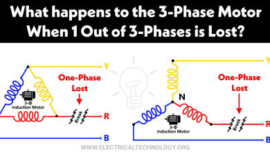
What happens to the 3-Phase Motor When 1 Out of 3 Phases is Lost?
What will happen to the 3-Φ Induction Motor Incase of Failure of 1 of the 3-Phases? A three phase induction motor must be connected to all the three phases for…
Read More » -
Stranded Wire vs Solid Wire. Which One is Best and Why?
Which One Carries More Current – Solid Conductor or Stranded Conductor? The war is still on and there is no winner yet between solid wire and stranded wire. One can…
Read More » -
Hopkinson’s Test – Circuit Diagram, Working and Applications
What is Hopkinson’s Test? Its Circuit Diagram and Operation in Motor Generator Set & Coupling What is Hopkinson’s Test? A Hopkinson Test is used to identify the efficiency of two…
Read More »