How to Wire ON-Delay Timer for 120V and 240V Load Circuits?
Wiring the AH3 ON-Delay Timer for 120V and 240V Circuits
Timers play a crucial role in automation and controlling the operation of appliances and machinery in both residential and industrial applications. They are used for precise control of sequential operations based on specific timeframes. These timers can be used for ON-delay, OFF-delay, or relay switching for specified durations. In the following wiring tutorial, we will guide you on how to wire and control an AH3 timer using 2-way and 3-way switches for ON-delay operations to control both 120V and 240V load circuits.
AH3-3 Timer
The AH3-3 timer is a type of industrial timing relay that operates within a specified time range, typically adjustable by the user. It is commonly used in control and automation applications to manage timing functions such as ON/OFF delay, pulse generation, or cyclic operation.
The “AH3-3” designation often refers to a specific model or series of timers produced by various manufacturers. These timers typically feature a digital or analog display for setting and monitoring time intervals, as well as control inputs and outputs (i.e. controlling the relays, motor, solenoid etc.) for seamless integration into automated systems.
Timers like AH3-3, SA3PA-B, H3BA, H3CR etc. are versatile devices used for ON-Delay, OFF-Delay and relay switching in various industries, including manufacturing, HVAC (Heating, Ventilation, and Air Conditioning), and process control, to facilitate precise timing and sequencing of operations.
Below are the terminal labels printed on the AH3-3 timer nameplate:
- Line (Phase or “+”) = Terminal 2
- Neutral (N or “-“) = Terminal 7
- COM “Common” = Terminals 8 & 1
- No “Normally Open” = Terminals 3 & 6
- NC “Normally Closed” = Terminals 4 & 5
Pins Connections of AH3-3 Timer
The diagram below illustrates the base terminals and their respective pin connections for the AH3 relay timer.
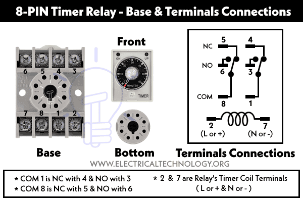
- Pins 2 and 7 = Energizing the relay’s coil via Phase and Neutral in AC or (+) and (–) thorough DC supply.
- Pin 1 is Common and Normally Closed with Pin 4 and Normally Open with Pin 3.
- Pin 8 is Common and Normally Closed with Pin 5 and Normally Open with Pin 6.
Ratings of the AH3 Delay Timer
- OFF-delay timers are employed when immediate activation of an appliance is required for a specified duration, with automatic shutdown once the predetermined delay period elapses.
- ON-delay timers are utilized to activate an appliance after a specified time, during which the appliance remains inactive. Once the delay period concludes, the load circuit is activated. Refer to our previous post about the comparison between ON-Delay and OFF-Delay Timers.
- Typical time settings range from 0 to 60 minutes, offering flexibility in operation.
- When dealing with 120V load circuits, ensure a wiring capacity of up to 6 amperes.
- For 240V load circuits, the maximum recommended wiring capacity is 3 amperes.
- To prevent overload, it’s essential to adhere to the load limits, such as 720W (calculated as 120V x 6A or 240V x 3A). Specifically, exercise caution when connecting devices like recirculation pumps, attic fans, or water pumps rated at 1/2 hp, 1/3 hp or 1/4 hp, as these inductive loads may draw high initial currents during startup.
How to Wire AH3-3 ON-Delay Timer for 120V & 240V Circuits?
Follow these steps to wire the AH3-3 ON-Delay Timer for either a 120V or 240V single-phase load:
- Ensure that the power supply to the circuit is switched off. If you are uncertain, simply switch off the main supply breaker in the main panel.
- Select the appropriately rated timer for your desired load circuit, whether it’s 120V or 240V.
- For a 120V load circuit, connect the Phase and Neutral terminals to the timer’s 2 and 7 terminals, respectively. For a 240V load circuit, connect Line 1 and Line 2 to the timer’s 2 and 7 terminals. In the case of DC control voltage, attach the + and – wires to the timer’s 2 and 7 terminals.
- Connect a pushbutton or switch (e.g., a 2-way or 3-way switch) to the Line wire, connecting it to terminal #2 of the timer. This switch controls the input signal and the operation of the timer, including turning it on and off.
- Depending on your circuit’s requirements, whether it’s an ON-Delay or OFF-Delay, connect the load circuit (e.g., motor, light point, buzzer, recirculation pump) to the timer using the common and either normally closed or normally open contacts (refer to the wiring diagrams for a clearer explanation).
- Adjust the delay time by rotating the timer’s knob to your desired value.
- When you activate the circuit by switching the external switch, the timer will begin counting down the pre-defined time set in the timer. The load points will become active when the delay time expires, which is why it’s called an ON-Delay timer.

Good to know: The wiring method for the AH3 timer is the same for both 120V and 240V load circuits, except that in a 120V circuit, the timer is connected to the Phase and Neutral, and in a 240V circuit, it’s connected to Line 1 and Line 2, respectively, to the 2 and 7 terminals of the timer.
In simple terms:
Timer Connection in a 120V Circuit:
- Phase wire connects to terminal 2.
- Neutral wire connects to terminal 7 of the timer.
Timer Connection in a 240V Circuit:
- Line 1 connects to terminal 2.
- Line 2 connects to terminal 7 of the timer.
Wiring the AH3 ON-Delay Timer using 2-Way Switch
In the following wiring diagram, we have used a single-pole switch to control the buzzer’s operation via an ON-delay mechanism using an AH3 timer.
In this circuit, when the operator switches ON the two-way switch, the light point will immediately illuminate as it is directly connected to the 120V power supply. Simultaneously, the delay timer begins operation and starts counting down the predefined time setting. When the delay time expires, the timer’s common terminal switches from NC (Normally Closed) to the NO (Normally Open) contacts, activating the circuit and causing the buzzer to start buzzing.
Click image or open in new tab to enlarge

If the operator turns off the single-pole switch, the buzzer will remain off. To reset the timer circuit and restart the delay, simply turn off the 2-way switch and then back ON.
Wiring the AH3-3 ON-Delay Timer using 3-Way Switch
In this wiring diagram, we have employed a three-way switch to control the ON-delay operation of the recirculation pump for the water heater using an AH3 timer. This configuration allows for activation of the timer’s circuit in any switch position of the three-way switch, whether it’s Up or Down.
When the operator changes the position of the three-way switch (either Up or Down), the load circuit will not start immediately. Instead, the timer circuit will activate and commence counting down the predefined time span. Once the set-up time elapses, the timer will trigger the load, causing the recirculation pump to start and circulate hot water to each bathroom.
Click image or open in new tab to enlarge

It’s important to note that the timer circuit remains continuously powered. When the operator switches the position to another, it resets and begins counting time anew. During this timeframe, the recirculation pump remains OFF due to the delay implemented in the ON operation through the timer. The timer can be completely deactivated via a circuit breaker or any other external switch used on the phase wire connected to the timer.
Good to know: If you have used small wire (like 18-gauge) for the switch and timer control, simply connect a 5-10A fuse as shown in the figure. In the event of a short circuit occurring on a 20A breaker (where 12-gauge wire is used and suitable for a 20A breaker), the entire current will pass through the 18-gauge wire. Therefore, the fuse will protect against overload and short circuit.
Related Posts:
- How to Wire AH3 OFF-Delay Timer and Relay with Boiler Fan?
- How to Wire Remote Control Countdown Timer?
- How to Wire Spring Wound Timer with LYS Rely for ON/OFF Delay
- How to Wire ST01 Timer for Dusk-Down On-Delay Light Control?
- How to Wire Twin Timer with Photo Eye Circuit for Time Delay?
- Difference Between ON Delay and OFF Delay Timer
- How to Wire ON/OFF Delay Timer for AC & DC Loads – 230V & 24VDC
- Automatic & Manual Control of 3-Phase Motor Using Delay Timer
- Wiring of DOL Starter for Automatic / Manual Control Using Digital Timer
- Automatic ON/OFF Circuit Using Two 8-PIN Timers for 1 & 3-Φ Load


