How to Find the Size of Earth Conductor, Earthing Lead & Earth Electrodes?
Calculate the size of Earth Continuity Conductor, Earthing Lead & Earth Electrodes?
For earhing or grounding purposes, the size of earth continuity conductor,, earthing lead and earth electrodes depend on wiring cables used in the system. Solved example given below will make the point easy to understand that how to determine the proper size of earth conductor, earth lead and earth electrodes in a specific installation.
Finding the Size of Earth Conductor, Earth Lead & Earth Electrode in Factory (Solved Example)
Below is the solved example for earthing & grounding installation in factory. The layout is shown below in fig 1.
Example: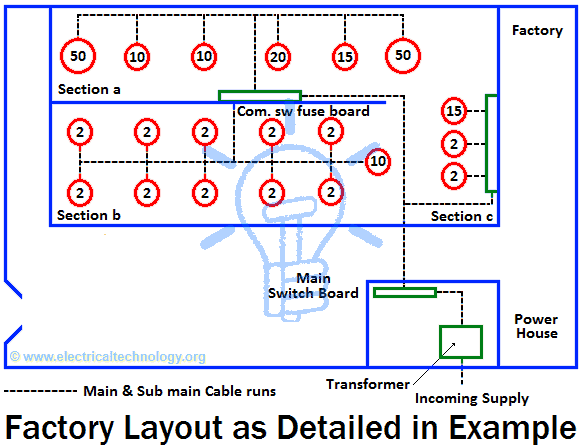
Find the proper size of earth conductor, earth lead and earth electrode for earthing and grounding system in the factory installations. Details and description of the given load (electric devices and equipment in the factory) as follow:
1. Motors
- 2 No of 50hp, 415V three phase induction motors and size of the cable connected to the motors is 19/.064.
- 1 No of 20hp, 415V, three phase induction motor and size of the cable connected to the motor is 7/.064.
- 2 No of 15hp, 415V, three phase induction motor and size of the cable connected to the motor is 7/.052.
- 3 No of 10hp, 240V, single phase induction motor and size of the cable connected to the motor is 19/.052.
- 12 No of 2hp, 240V, single phase induction motor and size of the cable connected to the motor is 7/.036.
2. Transformer
There is a 250kVA, three phase 11kV/400V (Step down) transformer installed in the factory which neutral have to be earthed. Size of the cables connected to LT (Low Tension) is 37/.083.
3. Water Level
Water level is deep about 30ft.
Solution:
Finding the Size of Earth Conductor:
Layout of the complete factory earthing and grounding system is shown in fig 2 below. Here, the biggest possible source of fault current is transformer, therefore, at least one earthing plate should be installed near to the transformer and the proper location for earth plate installation (for transformer) is shown in fig 2 (Position A).
Since the water level is deep about 30ft, therefore, we have to dig about 30ft coined and both of the plate can be installed in the same pit then (By doing so, we don’t need two pits as well as, it reduce the installation cost as well). However, for better safety purposes, another pit about 12ft can be dug (on Position B) near to position A for second earth plate installation. Also, make sure that water purring is possible when needed.
A connecting point near to main switch board is made at point C. The second point at D and third one at E which is right below the combination switch fuse board and above the cable ducting.
These points are connected via wires flowing through cable ducts. Since the example is fully related to the earthing of electrical apparatus only, therefore, there are two separately earth continuity conductor in whole factory (earth continuity conductors of other metalwork i.e. distribution fuse boards, switch fuses and other electrical wiring etc are not shown in the fig due to complexity)
- Also read: Types of Electrical Wiring
After proper selection of plates and connecting points, now we can find the proper size of earth continuity conductor and earth lead with the help of the following table no 1. In this table, suitable size of earth continuity conductor is given for each size of cable. For simplicity, the whole earthing scheme of the factory is divided in three sections. 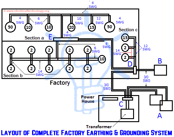
Explanation of each section is as follow:
Section A:
According to table 1
- Earth continuity conductor to 50hp motor (19/.064 cable) = 4 SWG
- Earth continuity conductor to 20hp motor (7/.064 cable) = 10 SWG
- Earth continuity conductor to 15hp motor (7/.052 cable) = 12 SWG
- Earth continuity conductor to 10hp motor (19/.052 cable) = 6 SWG
In this section, the biggest motor is 50hp, therefore, the central pair of earth continuity conductor should able to pass any value of fault current produce in the motor. In this section, since each motor of 50hp is installed on the far end of the distribution system, therefore, the size of each earth continuity conductor around this section 4SWG. The proper sizes of earth continuity conductors for other small motors to the main pairs also given in table 2.2.
Section B:
According to the table, the earth conductor sizes are as follow for this section.
- Earth continuity conductor to 10hp motor (19/.052) = 6 SWG
- Earth continuity conductor to 2hp motor (7/.036) = 14 SWG
The distribution system in this section is designed such a way that the size of each earth continuity conductor (from 10Hp motor to the connecting point E) is 6 SWG but, for 2Hp motors, the size of earth conductor is 14SWG. There would be a safe path, if fault occurs at 10Hp motor side.
Section C:
The size of earth continuity conductors for this section is as follow:
- Earth continuity conductor to 5hp motor (7/.052) = 12 SWG
- Earth continuity conductor to 10hp motor (7/.036) = 14 SWG
The size of earth continuity conductor from 15Hp to connecting point D is 12SWG while for 2Hp (each) motor, the conductor size would be 14SWG.
Related Posts
- How to Find the Proper Size of Circuit Breaker? Breaker Calculator & Examples
- How to Find Voltage & Ampere Rating of Switch, Plug, Outlet & Receptacle
- How to Find The Suitable Size of Cable & Wire for Electrical Wiring Installation
Finding the Size of Earth Leads:
Now we can find the proper size of earthing leads. Since the cable size of transformer on L.T side is 37/.083. So we can use 3/0 SWG copper wire (or 3/16 x ¾ or 1/8 in) Copper strip. If fault occurs at transformer, then fault current will flow through the earth plat A or B or both at once and it depends on the earth resistance as well.
Therefore, the earth leads should able to pass the fault current. For this purpose, we should use 3/0 SWG for all earth leads from transformer to C, C to A, C to D, and D to B. Since the Transformer fault current will not flow in wires between E to D, therefore, it size should be 4SWG (which is equal to the big earth continuity conductor connected to E).
Finding the Size for Earth Plates & Earth Electrodes
Since both earth plates are below from water level, therefore, 2ft x2ft x 1/8 plate size is most suitable for each main and secondary plate. Continuity should be well after testing the system but also consider the earth resistance as well.
If the earth resistance increases than 1Ω, in that case, additional plates can be used in parallel with secondary plate to minimize the total resistance of earthing and grounding system.
Table 1. Earthing Conductors
Size of copper wire and Strip for earth continuity conductor and earth leads.
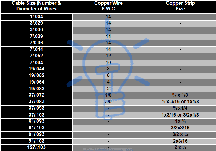
Table 2.
Size of Earth Wire in SWG and Earth Electrode for Motors and Other Electrical Apparatus, Devices and Equipment.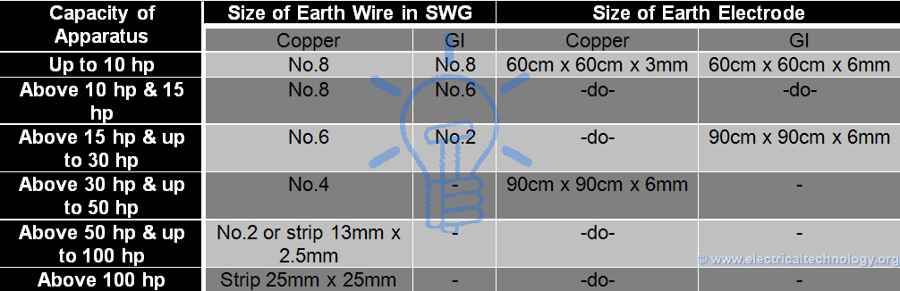
Note: Perform a continuity test for earthing installation to make sure everything is working as expected.
Related Posts:
- Difference Between Grounding, Earthing and Bonding
- Difference between Real Ground and Virtual Ground?
- Difference Between Neutral, Ground and Earth
- How to Find the Size of Earth Conductor, Earthing Lead & Earth Electrodes?
- Design of Grounding / Earthing System in a Substation Grid
- Different Types of Electrical Wiring
- Step by Step Home Electrical Wiring Installation Tutorials
- The purpose of Earth or Ground wire in overhead Transmission lines.


I like this
How to make elemant
On beginning of your calculation you should describe standard as a base of your calculation. Used by you measurement units used only in USA (ft= foot) suggest that this calculation is applied to the US industrial plant – but whole calculation and others measurements units are not American’s and calculation is not provided to follow NEC (NFPA70) requirements.
With out it your work is only an assembly of words.
Example: White insulated wire is grounded wire. In USA YES it is, but under many other grounded wire might be black (Australia) or blue (EU) or Red.
MML
Thank you for positive feedback…. We will include all the necessary information in the articles. Once again thanks.
zigale2010@gmail.com
you are a real technocrat serving the community free of cost thanks
i well improve my E L
You have been helpful to me so much thankyou have learnt alot from your updates continue updating me. God bless
Electrical electronics component tasting
Please upload NEC rules and regulations